
Tender
SP&S #273
Astoria RR
Work Photos
Early Photos
History
Events
Join
ARPA
Links
Contact Us
Home
|
|
|
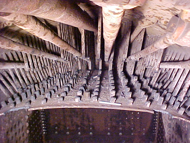
Crown Sheet Removal
Wednesday, December 4, 2002 by Martin AdamsHere is an rare view of the top of the firebox crown sheet from inside the boiler, looking to the rear. We are in the process of flame cutting the radial crown staybolts to free the crown sheet from the boiler wrapper sheet (the outside of the boiler). This picture gives us a good view of the various components of locomotive boiler construction. In the foreground is the 3/8” thick crown sheet. On #21, the crown sheet and the two side sheets are on piece, but we refer to them separately so we can identify where work is being done. We have already removed the side sheets and what you see on either side below the crown sheet is the “water side” or inside of the boiler wrapper. The dark metal in the rear is the pieces that we have formed to replace the damaged portions of the wrapper. The new sheets meet the old win an “x-ray quality full penetration weld. Seven eighths inch rivets will replace the bolts that you can see running vertically in the back corners, but the firebox side sheet had to be removed first to get the rivet guns inside the boiler. Along the front edge of the crown sheet you can see the old rivet holes where the firebox flue sheet was joined to the crown sheet. In the middle of the crown, behind the first row of cut stay bolts you can see the fusible plug (it looks like a small upside down flower pot). This is a brass plug that is placed in the highest point in the firebox. It has a hole through it that is filled with lead. Lead melts at 600 degrees Fahrenheit, considerably below point at which steel begins to loose its strength (about 1600 degrees Fahrenheit). If for some reason, the water level in the boiler should get so low as to no longer cover the crown sheet, the lead in the fusible plug would melt and steam would begin to dump into the firebox. This great rush of steam would put out the fire and alert the crew to the impending disaster. While now worthy train crew should ever experience this event, it is designed to put out the fire before the crown sheet could weaken and fail resulting in a catastrophic boiler explosion. Above the crown sheet, you can see the hundreds of stay bolts. The ones in the front have been cut while the ones in the rear are still intact. We cut out a chunk of the stay bolt to make room for the torch to reach the rows behind. Running fore and aft in the tow center is the 2 1/2 “ dry pipe that feeds steam to the “turret” on the top of the boiler immediately ahead of the backhead. The turret is a manifold with a number of valves to control various steam driven appliances such as the air compressor, hydrostatic lubricator, turbine generator (dynamo), injectors, blower, etc. Also running fore and aft in the upper part of the picture are the diagonal braces. They secure the upper part of the backhead, that portion that is higher than the top of the firebox that cannot be secured with staybolts. They are fastened between the wrapper and the backhead using clevis and pins attached to large “t-irons” that are riveted in place.
More Photo NEWS